TANGLEY CALLIOPE RESTORATION PROJECT (part 10)
by Dr. Bill BlackRESTORING THE AIR MOTOR VACUUM CONTROL
This month our project is the restoration of the unit which controls the speed of the vacuum air motor to power the roll frame. This unit is a simple type of slider valve which serves to increase or decrease the amount of vacuum which is applied to the air motor. The greater the amount of vacuum applied to the air motor the faster it runs and hence the greater the speed at which the music roll passes over the tracker bar.
PHOTO A shows this control unit before disassembly. Take note of the rod extending from the unit on the left side. Attached to this rod is an arm indicated by an arrow in the picture. Also shown in the picture are the vacuum inlet and the outlet which goes to the air motor.
In PHOTO B, the top of the unit has been removed to expose the internal parts. Attached to the rod is a block. This block can be moved back and forth by means of moving the arm attached to the rod (shown with the arrow in PHOTO A). The vacuum inlet nipple is positioned over a slot in the bottom of the unit. The block can be moved back and forth over this slot to determine the amount of the slot uncovered according to the position and controls the amount of vacuum to be applied to the air motor. The block moves over a leather facing on the bottom of the unit. Graphite is applied to the block and leather to provide smooth movement. The joints of the unit were checked for leaks, a new gasket made for the top and the unit screwed shut.
PHOTO C shows the shelf on which the roll frame and air motor are positioned. The shelf was cleaned of the oil accumulation from the roll frame and new finish applied.
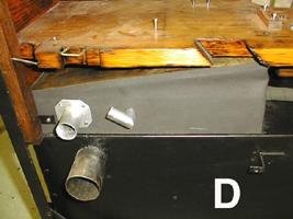
PHOTO D shows the vacuum reservoir installed on the top of the pressure tank. We have also installed the wooden sides of the calliope. These were also cleaned, sanded and a new finish applied.
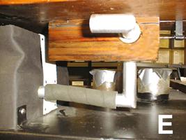
In PHOTO E, we see the air motor vacuum control installed on the underside of the shelf. The vacuum nipple on the bottom of the unit connects to the vacuum reservoir. The top nipple will supply vacuum now regulated by the control unit to the vacuum air motor.
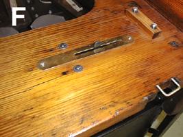
PHOTO F shows the top of the shelf. You can see the arm which we pointed out in PHOTO A protruding slightly through the shelf. This arrangement allows the operator to move the arm back and forth to control the speed of the music roll. This arm is accessed by inserting your fingers under the take up spool on the roll frame.
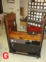
PHOTO G shows what we have accomplished so far. Also visible are the wood sides of the machine which are now in place.
Dr. Bill Black is one of the nation's most knowledgeble Wurlitzer band organ experts. He has made recordings of many band organs and other mechanical music machines which are available for purchase in our CarouselStores.com website.