TANGLEY CALLIOPE RESTORATION PROJECT (part 12)
by Dr. Bill BlackFINISHING THE AIR MOTOR
Having disassembled the air motor and cleaned the individual parts, the next step is to recover the pneumatics. These are recovered the same way as the stack pneumatics except we will use motor cloth which is a bit heavier than the material used for the stack pneumatics.
In PHOTO A we see the pneumatics recovered, painted and joined together by means of the nipples in the center of each pneumatic and metal strips. The top surface of the blocks where the sliders move back and forth have been block sanded to insure a flat surface for these sliders.
In PHOTO B the air motor has been completely reassembled. The holes in the ends of the wooden rods have been rebushed, slid onto the crankshaft and the other ends attached to the pneumatics . The outermost pneumatics each have a bracket mounted on the top to support each end of the crankshaft and serve as a central bearing. The right side of the crankshaft has a sprocket which will have a ladder chain connecting to the sprocket on the roll frame. The slider valves have been mounted on the pneumatics. Each side of the slider has a wire bracket to hold it in place as they move back and forth.
PHOTO C shows the air motor from another view.
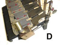
PHOTO D shows a closer view of the slider valves. Note the connection between the valve and the wooden arm connected to the crankshaft. This consists of wire rods which are threaded and screwed into a wooden dowel. This arrangement provides a means to either lengthen or shorten this link between the wooden arm and the slider by screwing the wire rod in or out. This adjustment allows the timing of the sliders to be adjusted to allow a smooth sequence of the pneumatics opening and closing and provide a constant rpm of the crankshaft. Note the wooden block with the two nipples on it. The nipple on the lower side is the inlet for the regulated vacuum to the air motor coming from the vacuum control discussed in part 10. The nipple on the top is the inlet for the vacuum supply to increase the speed of the air motor for the rewind function of the roll frame.
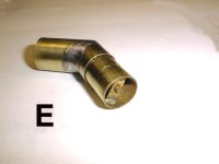
PHOTO E shows a closeup view of the inside of the top nipple. Inside this nipple is a check valve. This internal valve serves to seal off this nipple when the lower nipple has vacuum applied to it and the upper nipple does not. In this mode, the vacuum is directed to the air motor from the vacuum control box and prevents leakage through the top nipple. This nipple is connected to the unit which controls the rewind vacuum supply and the stack cutout. When the higher level of vacuum for rewind is applied to the top nipple, the check valve opens and causes the air motor to operate at a higher speed for the rewind function.
Dr. Bill Black is one of the nation's most knowledgeble Wurlitzer band organ experts. He has made recordings of many band organs and other mechanical music machines which are available for purchase in our CarouselStores.com website.