TANGLEY CALLIOPE RESTORATION PROJECT (part 20)
by Dr. Bill BlackTHE STACK CUTOUT
This pneumatic mechanism serves three functions. It shuts off the vacuum supply to the stack so the notes on the music roll do not play during rewind, supplies unregulated vacuum to the air motor for the rewind phase and to supply vacuum to operate the take up spool brake shoe.
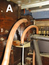
PHOTO A shows the unrestored stack cutout in the calliope before it was removed.
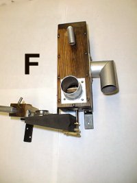
Take a quick look at PHOTO F at this point to note the various components of the unit.
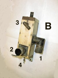
PHOTO B shows the cutout removed from the calliope. The finish on the wood has been removed. The unit is composed of a box with three chambers. It has an internal valve which can channel the vacuum to either the top chamber or the bottom chamber. The middle chamber is connected to the vacuum reservoir located on top of the large pressure tank. This reservoir is connected directly to the vacuum pump so the cutout middle chamber (nipple 1) receives full vacuum (unregulated vacuum) from the pump.
The internal valve is spring loaded (4) so as to keep the vacuum channeled out nipple 2 during the play mode. Nipple 2 is connected to the stack. As discussed last month, the rewind pneumatic contains a valve to supply atmospheric pressure to operate the pneumatic valve assembly attached to the cutout unit (PHOTO F). When the pneumatic collapses, it pushes up on the rod ( 4) attached to the internal valve. The valve is forced up to shut off the vacuum to the lower chamber and apply vacuum to the upper chamber.
The upper chamber has two outlets (only one is visible in the photos). The nipple 3 is connected to the pneumatic which operates the brake shoe on the take up spool. The other nipple which is not visible is connected to the vacuum motor. This supplies the air motor with full vacuum to produce a fast speed for the rewind.
When the rewind shifter returns to the play mode, the atmospheric pressure to the valve on the cutout is shut off, the pneumatic opens and the spring (4) forces the internal valve downward to again restore vacuum to the lower chamber and shut off the vacuum to the upper chamber. The cycle is completed.
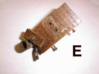
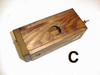
PHOTO C shows the wooden portion of the cutout stained and refinished.
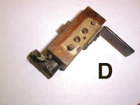
PHOTO D shows the mounting block for the pneumatic valve which operates the cutout.
PHOTO E shows the top of the block. We have removed the small wood cover to expose the bleed cup for the valve. This provides access to clean out the bleed if necessary.
PHOTO F shows the completed unit.
Dr. Bill Black is one of the nation's most knowledgeble Wurlitzer band organ experts. He has made recordings of many band organs and other mechanical music machines which are available for purchase in our CarouselStores.com website.