TANGLEY CALLIOPE RESTORATION PROJECT (part 6)
by Dr. Bill BlackMORE DISASSEMBLY
In a previous article, I mentioned that I had removed the brass pipework from the calliope. In PHOTO A we can see the top of the calliope with the pipework removed. Each pipe is mounted on a threaded insert which is soldered into a hole in the top. These inserts are carefully checked to be sure that none are loose. Later we will strip the paint from the top and repaint it. We want to be sure we don¹t have to go back and resolder any of these inserts after the new paint is applied. These inserts can be broken loose if excessive force is applied to them. Some of the longer pipes can exert enough leverage on the solder joint to break it loose if the machine gets rough handling. The previous owner built a special cabinet to store the pipework when traveling to a show for this reason. The larger pipes have enough weight to break this joint if the truck has a bumpy ride to the show and they are rocked back and forth.

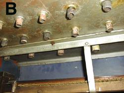
PHOTO B shows the underside of the top and the inserts projecting through the top. The hoses to the windchest are connected to these inserts. They vary in size according to the size of the brass pipe screwed into the top of the insert.
IN PHOTO C, all the tubing to the pipework is removed and we can see the back of the stack and the back of the windchest.

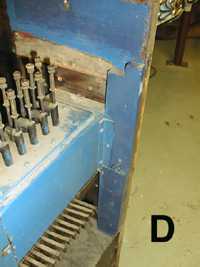
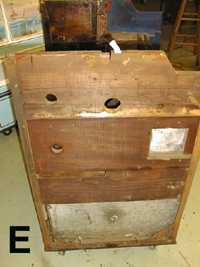
The Tangley has some interesting and nice aspects to the design and also has some rather rough areas too. In PHOTO D we can see the method of mounting the windchest in the machine. A large square hole is cut into the wooden sides of the case and the windchest rests in these holes. On each end of the windchest is a metal mounting bracket which is screwed into a wooden strip attached to the angle iron side of the frame. This provides a sturdy attachment to the frame. However, the windchest is a rather loose fit in the holes in the wooden sides. PHOTO E shows the side of the machine with the sheet metal covering removed. The square hole for the windchest is shown. Since these wooden sides were covered by sheet metal, top grade lumber was not used for these sides.
PHOTO F shows a closer view of this arrangement. Note the use of small wooden wedges to force a tighter fit to the windchest in the square hole. I assume that is the original method of mounting the windchest. These wedges have small nails in them to be sure they don¹t fall out of place. Later on we will see another use of wedges to mount and stabilize the pressure tank. This arrangement is not too pretty, but I guess I should not criticize it since it appears to have worked in these machines.
Dr. Bill Black is one of the nation's most knowledgeble Wurlitzer band organ experts. He has made recordings of many band organs and other mechanical music machines which are available for purchase in our CarouselStores.com website.