TANGLEY CALLIOPE RESTORATION PROJECT (part 8)
by Dr. Bill BlackBEGINNING THE RESTORATION WORK
In PHOTO A we can see the top of the pressure tank where we have removed the pressure spill valve. This base of the valve has a steel plate with nuts and bolts to attach it to the tank. Several of these bolts have the threads stripped. The bolts are soldered to the top of the tank and you need to unsolder them to replace the stripped bolts.
In PHOTO B the tank has been removed from the frame and placed on saw horses. Several coats of paint have been removed from the outside of the tank. In the upper right side you can see the repaired bolts. For many years, the original Roots blower was used to supply pressure and vacuum for the calliope. The blower tends to produce a fine oil mist as a byproduct of its operation. So, over the years this had caused an accumulation of a one quarter of an inch thick coating of goo in the bottom of the tank. We took the tank to a steam cleaning company to have this material removed. Unfortunately, they did not have a wand to get the steam over the entire inside. The part you could see thru the hole where the relief valve was removed looked great. But, closer inspection with a flashlight showed that most of the goo was untouched. So, the tank came home and I pondered another method. I then took a gallon of water wash up paint remover and poured it in the tank. I then took duct tape and closed up the external openings in the tank. Several times during the day I would slosh the paint remover around in the tank. After about a day of this, I used a water pressure washer to rinse out the paint remover. This worked very well and the goo was eliminated.
There are a lot of parts in the calliope which depend on sheet metal fabrication skills. The pressure tank is a example of this. The tank is closely inspected for air leaks. When the tank was constructed it was riveted and then soldered together. There are struts inside which are used to strengthen the sides of the tank. These were soldered into place before the tank was finally soldered shut. One of the struts had broken loose from the side farthest away from the access hole. How to reattach this was a problem. The solution was to drill a hole in the side where the broken strut attached to the side and insert a bolt through the end of the strut and the side of the tank. A nut was secured to the bolt and soldered to the side of the tank. The broken strut is now secured to the tank side.
PHOTO C shows the finished pressure tank. I used a satin black oil base paint on the tank.
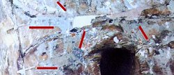
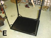
Now we turn our attention to the frame. As we mentioned last month, the frame is constructed from angle iron which is welded onto a sheet metal base and reinforced with braces at the corners (PHOTO D). The upright leg in the lower right side shows the slight kink about one foot up from the bottom. As also mentioned last month, this was apparently due to a blow to this area which was sufficient to bend the leg. We rigged up sort of a rigid support with wood and clamps to support the leg below the kink and then take advantage of leverage to bend the leg above the kink to straighten the leg. This was done a bit at a time with checking to see that the frame was going to end up being square with the other legs. We also checked this against the wooden sides of the case and the top to be sure everything was going to fit together at the end. After this straightening process, we wire brushed the frame to remove the rust, dirt and old paint. PHOTO E shows the finished frame, also painted with the satin black paint.
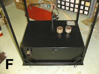
In PHOTO F, the tank has been mounted in the frame by means of the wooden wedge arrangement described previously. I also made a wooden base with casters to hold the machine so it could be easily moved around as we work on it.
Dr. Bill Black is one of the nation's most knowledgeble Wurlitzer band organ experts. He has made recordings of many band organs and other mechanical music machines which are available for purchase in our CarouselStores.com website.