TANGLEY CALLIOPE RESTORATION PROJECT (part 23)
by Dr. Bill BlackTHE VACUUM AND PRESSURE SUPPLY
Next we will build the unit which will provide wind pressure and vacuum for the calliope. Rather than use the Roots blower which came with the calliope, we will use a smaller and lighter unit.
This unit was actually constructed several years ago. The late Mike Kitner also had a Tangley which he planned to restore. Mike had designed this unit and used it before on calliopes. Mike and I built two of these units at the same time. They were basically the same except for a few small items. I installed a vacuum gauge on mine so I could see what the vacuum level was when the machine was playing. I also installed an electrical outlet to plug in a strobe tuner and a work light.
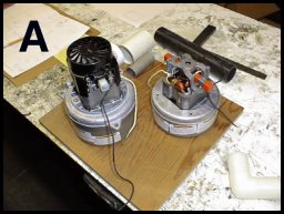
We used two vacuum motor pumps. One has a captured exhaust which allows it to supply wind pressure. PHOTO A shows these two motors positioned on a mounting board. This allows us to see what size box will be required to house the motors. The larger motor is the one used to supply the wind.
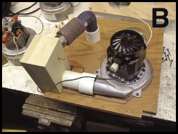
PHOTO B shows the wind motor positioned on the board. It was necessary to route out a space on the board to enable the motor to be mounted on the board. (This space can be seen on PHOTO C.) The large solid block of wood on the left of PHOTO B serves as an inlet and outlet junction for the vacuum and wind. The large hose and angle visible on the top of the photo serves to connect to the vacuum motor which will be mounted on the other side of the board. The small nipple on the wood block will be connected to a vacuum gauge.
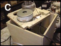
PHOTO C shows the motors mounted on the board and the box enclosure constructed out of plywood with corner cleats to support the sides. The center board with the motors will be positioned in the center of the box.
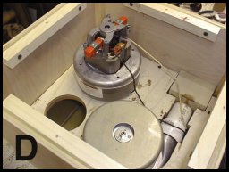
In PHOTO D we see the board with the motors mounted in the box. This photo is as seen from the bottom of the box. Cleats have been installed on the lower part of the sides in order to mount the bottom of the box.
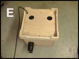
PHOTO E shows the bottom attached to the box. A base is also constructed for the box. This is designed to slide up or down a bit to allow the unit outlet nipples to be aligned to the nipples on the calliope. After the height alignment is determined, the base is screwed onto the box. In the photo, the outlet nipples for the vacuum and the wind are visible. These nipples are inserted through the side of the box into the large wooden block inside.
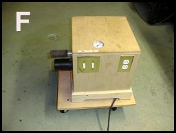
In PHOTO F, the completed unit is shown. It has switches to turn the vacuum or the wind motor on or off. If you want to play the calliope by hand, the vacuum motor does not need to be operating. Also visible is the electrical outlet and the vacuum gauge mounted on the top. We use a 110 volt light switch dimmer to regulate the speed of the vacuum motor and the vacuum level produced. The adjustment for the dimmer is accessed through a small hole in the side of the case. This is visible between the switches and the electrical outlet.
The entire unit is mounted on a small dolly which matches up with the dolly for the calliope. To connect the unit to the machine, just slide the unit up to the calliope and push the hoses onto the nipples on the calliope.
Dr. Bill Black is one of the nation's most knowledgeble Wurlitzer band organ experts. He has made recordings of many band organs and other mechanical music machines which are available for purchase in our CarouselStores.com website.