TANGLEY CALLIOPE RESTORATION PROJECT (part 25)
by Dr. Bill BlackINSTALLING THE STACK
This month we will begin to install the internal components. PHOTO A shows the pneumatic stack after we completed it some months ago.
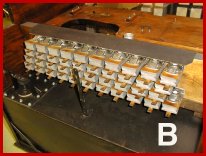
In PHOTO B we have installed the stack in the calliope. We use a strip of motor cloth tacked onto the top of the stack to act as a dust cover to protect the top facings on the stack valves from debris. The upright brace shown in the photo will act as a support for the center of the stack linkage which will be installed later.

PHOTO C is a back view of the installed stack. The stack is fastened to the case by means of cleats which are bolted to the ends of the stack and then the cleats are bolted to the sides of the case. On the top of the back side of the stack you can see the vacuum inlet nipple for the stack. The small nipples for the connection to the trackerbar are also visible at the bottom of the stack. On the right side of the photo are the two wind pressure outlets on the top of the pressure tank which will be connected to the windchest by means of two large tubes. The tops of the outlets are protected by some duct tape to prevent me from dropping something into the pressure tank by accident.
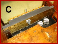
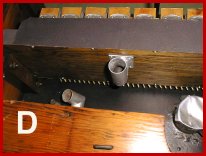
PHOTO D shows a closer view of the back of the stack. Visible just below the shelf for the roll frame are two nipples from the vacuum reservoir. The larger nipple supplies vacuum to the stack cutout (which controls the vacuum to the stack nipple) and the smaller nipple is a vacuum supply to operate the control valve and pneumatic to operate the stack cutout.
In PHOTO E we have removed the pressure relief valve from the top of the pressure tank. This was cleaned up, painted and a new facing made from a piece of shoe sole leather. This valve assembly is attached to the top of the pressure tank with bolts soldered to the tank. The valve assembly is placed over the bolts and the nuts are secured to attach it to the tank.
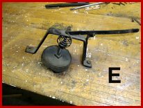
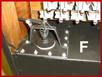
PHOTO F shows the relief valve installed on the tank. The disc with the leather facing is spring loaded. By adjusting a nut on the threaded stem, the pressure on the valve can be varied by the amount of compression on the spring. More spring pressure causes the wind pressure to spill off at a higher value. So, by means of the adjustment, the operating wind pressure of the calliope can be set.
Dr. Bill Black is one of the nation's most knowledgeble Wurlitzer band organ experts. He has made recordings of many band organs and other mechanical music machines which are available for purchase in our CarouselStores.com website.