TANGLEY CALLIOPE RESTORATION PROJECT (part 28)
by Dr. Bill BlackINSTALLING INTERNAL PARTS
We can now proceed to install some of the internal parts which were restored some month ago. PHOTO A shows a back view of the installed roll frame. The shelf on which some of these parts are mounted has a cutout area to allow clearance for the two large pressure feeder tubes from the pressure tank to the windchest.
PHOTO B show a front view of shelf on which the roll frame is mounted along with the air motor. The roll frame is finished but the trackerbar tubing has not yet been installed. The small pneumatic on the lower left side of the frame operates a braking system to keep the slack out of the music roll during play and rewind. When the frame is in the play mode, a spring keeps a brake shoe in contact with a wheel on the supply spool axle. This provides a drag on the supply spool and keeps slack in the paper from occurring on the takeup spool. When the rewind mode is engaged, the pneumatic collapses, pulls another brake shoe into contact with a wheel on the takeup spool. At the same time, the brake shoe on the supply spool is pulled away from the wheel releasing the drag on the supply spool. This acts to prevent slack in the music roll from occurring during the rewind phase.
In PHOTO C, we see another view of some of the control units mounted in the case. The part marked 1 is the rewind-play unit. The part marked 2 is the stack vacuum cutout. The part marked 3 is the air motor which powers the roll frame. The operation is as follows. When the rewind hole in the music roll passes over the hole in the tracker bar, the valve on the rewind pneumatic, 1, is triggered and the large pneumatic collapses and the roll frame is shifted into the rewind mode. The pneumatic also opens as small pallet valve and triggers the valve and a pneumatic on the stack cutout unit, 2. When this occurs, the vacuum to the stack is interrupted so the music roll does not play during the rewind phase. At the same time, full vacuum is applied to the air motor, 3, and the roll frame operates at high speed for the music roll to rewind more quickly than the speed of the play mode. At the end of the rewind, the play hole in the music roll triggers another valve in the rewind unit, the large pneumatic is released, a spring pulls open the pneumatic and the roll frame shifts back to the play mode, the stack cutout valve shifts to the play mode and vacuum is again restored to the stack. At the same time, a check valve in the high vacuum inlet of the air motor closes and the vacuum to the air motor is now routed back to the regulated vacuum source so the the music roll speed can be adjusted.
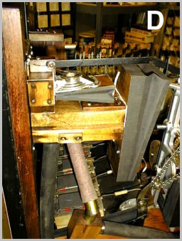
PHOTO D shows a closer view of the rewind-play unit.. Note the latch arrangement on top of the large pneumatic which holds the unit in the rewind mode during the rewind. When this latch is released, the roll frame returns to the play mode.
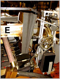
PHOTO E shows the side of the roll frame with the gear arrangement. Note the ladder chain which connects the air motor to the roll frame. Also visible is the spring which pulls the rewind pneumatic to the open position when the latch is released and the roll frame returns to the play mode.
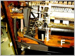
In PHOTO F, we have installed some the tubing to these various components. At this point it begins to look like we are making some real progress in the project.
Dr. Bill Black is one of the nation's most knowledgeble Wurlitzer band organ experts. He has made recordings of many band organs and other mechanical music machines which are available for purchase in our Carouselstores.com website.