TANGLEY CALLIOPE RESTORATION PROJECT (part 9)
by Dr. Bill BlackRESTORING THE VACUUM RESERVOIR
PHOTO A shows the vacuum reservoir as it is positioned in the calliope before we dismantled the calliope. This reservoir is mounted on top of the pressure tank and positioned under the shelf for the roll frame and air motor.
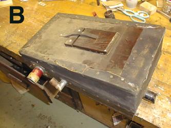
In PHOTO B, the unit has been removed from the machine. The large nipple is for the main vacuum supply from the blower. The smaller nipple serves to supply the rewind pneumatic control for the roll frame. On the front of the reservoir is a supply nipple for the air motor which runs the roll frame. On the top is the spring loaded spill valve.
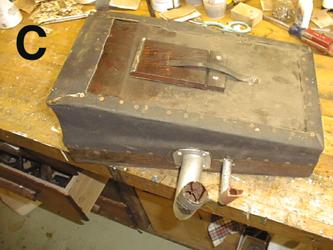
In PHOTO C we see the other side of the reservoir. The large nipple supplies vacuum through the rewind cutout to the stack valves. The smaller nipple supplies vacuum to operate the cutout unit to stop the vacuum to the stack during the rewind phase. In an effort to insure that the cloth remains attached to the wood in an earlier repair, someone has used a lot of tacks. This is not necessary if the wood has been properly cleaned prior to recovering and the glue is used properly.
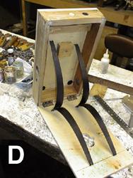
PHOTO D shows the vacuum reservoir with the old cloth removed, the wood surfaces sanded and ready for the new covering. Heavy motor cloth was used to cover the reservoir with hot glue being used. The springs were cleaned and repainted. Note the metal hinges joining the top to the frame. These are employed to strengthen the hinge end of the pneumatic. As these springs are always trying to force the bellows to the open position, wood clamps were used to hold the bellows in the desired amount of opening while the new cloth is glued into place.
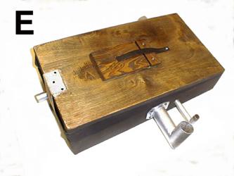
In PHOTO E we see the completed restoration of the reservoir. We have used a cloth web strap to limit the amount of opening of the reservoir to prevent it from using the shelf above as a limiter. This would put a lot of stress on the shelf due to the force of the reservoir top in an upward direction. During the restoration of the reservoir, we noticed the rather large clover-leaf shaped hole in the top, under the spill valve. This shaped hole was allowed to remain which later proved to be a mistake. The shape of the hole can be seen in PHOTO D.
Inside the reservoir is a vertical dowel attached to the base which can contact the underside of the spill valve. As the reservoir collapses, at a certain point before the reservoir is completely closed, the spill valve is forced open by this dowel. This arrangement allows excessive vacuum to bleed off and to maintain a reserve supply of vacuum to cope with the fluctuating demand to operate the machine.
Dr. Bill Black is one of the nation's most knowledgeble Wurlitzer band organ experts. He has made recordings of many band organs and other mechanical music machines which are available for purchase in our CarouselStores.com website.