
 Why did I build a band organ? Well, the simple answer would be that I
had a desire to own one and buying one can be an expensive proposition.
But more important for me was the idea of creating a band organ from
basic materials and the sense of accomplishment that would bring. I had
restored a number of player pianos and a player reed organ but this
project would be different in that I would be starting from "scratch".
Actually I had something smaller in mind. For several years I had
considered building a street organ or monkey organ but could not find
suitable plans. Then about three years ago I learned that plans were
available for a replica of a Wurlitzer 105 band organ. I obtained a set
of the plans and after studying them for a few days I said, "I can do
that." There were a couple of items such as the crankshaft and roll
frame that were probably beyond my metalworking abilities but it was my
understanding that there were some individuals out there that could
provide those items!
Why did I build a band organ? Well, the simple answer would be that I
had a desire to own one and buying one can be an expensive proposition.
But more important for me was the idea of creating a band organ from
basic materials and the sense of accomplishment that would bring. I had
restored a number of player pianos and a player reed organ but this
project would be different in that I would be starting from "scratch".
Actually I had something smaller in mind. For several years I had
considered building a street organ or monkey organ but could not find
suitable plans. Then about three years ago I learned that plans were
available for a replica of a Wurlitzer 105 band organ. I obtained a set
of the plans and after studying them for a few days I said, "I can do
that." There were a couple of items such as the crankshaft and roll
frame that were probably beyond my metalworking abilities but it was my
understanding that there were some individuals out there that could
provide those items!
 Starting the project it seemed to me that the most critical items would
be the pipes. It would be extremely frustrating to build the case,
bellows, etc. first and then find out that one could not build a pipe
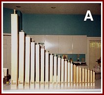
that worked. So based on that I decided to build a few smaller pipes
just to see if I could. I started with one of the smaller stopped flutes
from the melody section. In PHOTO A these would be the small pipes at
the right. The large pipe to the left is approximately four feet long
which will give you some idea of the size of the other pipes. After
assembling the pipe I tested it by blowing with my mouth, not really the
way to test pipes but I will have more to say about that later. To my
amazement it actually made a sound, and a pleasant sound at that. This
was encouraging. I put together five more pipes in that section. I was
able to tune them to the proper pitch using an electronic guitar tuner as
a guide. However, the only source of wind I had was my own breath and
that is not a controllable or constant pressure. Organ pipes are voiced
and tuned to operate at a specific air pressure. If the pressure is
increased the pitch will also rise. If the pressure is decreased the
pitch of the note will drop. If I were to continue it would be necessary
to have some sort of test box to provide a constant source of air
pressure and a valve for turning it on and off. I should mention at this
point that after successfully constructing a few small pipes I decided to
try something larger and ended up building the largest pipe in the organ,
the four foot bass G pipe at the left in the picture above.
Starting the project it seemed to me that the most critical items would
be the pipes. It would be extremely frustrating to build the case,
bellows, etc. first and then find out that one could not build a pipe
that worked. So based on that I decided to build a few smaller pipes
just to see if I could. I started with one of the smaller stopped flutes
from the melody section. In PHOTO A these would be the small pipes at
the right. The large pipe to the left is approximately four feet long
which will give you some idea of the size of the other pipes. After
assembling the pipe I tested it by blowing with my mouth, not really the
way to test pipes but I will have more to say about that later. To my
amazement it actually made a sound, and a pleasant sound at that. This
was encouraging. I put together five more pipes in that section. I was
able to tune them to the proper pitch using an electronic guitar tuner as
a guide. However, the only source of wind I had was my own breath and
that is not a controllable or constant pressure. Organ pipes are voiced
and tuned to operate at a specific air pressure. If the pressure is
increased the pitch will also rise. If the pressure is decreased the
pitch of the note will drop. If I were to continue it would be necessary
to have some sort of test box to provide a constant source of air
pressure and a valve for turning it on and off. I should mention at this
point that after successfully constructing a few small pipes I decided to
try something larger and ended up building the largest pipe in the organ,
the four foot bass G pipe at the left in the picture above.
 I considered building a test box for voicing and tuning each pipe as I
constructed them, but opted instead to go ahead with the wind chest. The
pipe feet sit in the wind chest and inside the chest there is a valve for
each note, therefore it could be used for testing without having to build
a separate test fixture. For an air supply I purchased a blower box from
the Player Piano Company in Wichita, Kansas. The blower box has a motor
speed control so that it can be adjusted to provide the correct amount of
pressure, in this case 8 inches of water. In pounds per square inch this
would be less than one psi. An organ does not require a very high
pressure but does need a fair volume of air.
I considered building a test box for voicing and tuning each pipe as I
constructed them, but opted instead to go ahead with the wind chest. The
pipe feet sit in the wind chest and inside the chest there is a valve for
each note, therefore it could be used for testing without having to build
a separate test fixture. For an air supply I purchased a blower box from
the Player Piano Company in Wichita, Kansas. The blower box has a motor
speed control so that it can be adjusted to provide the correct amount of
pressure, in this case 8 inches of water. In pounds per square inch this
would be less than one psi. An organ does not require a very high
pressure but does need a fair volume of air.
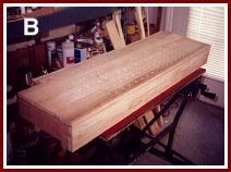
 Parts of the organ that need to be airtight, such as the wind chest, are
usually made of a dense, low porosity wood. Maple is an excellent choice
for this application. In addition it is a strong wood not prone to
splitting. PHOTO B shows the beginnings of the chest. If you look
closely you can see holes drilled in the top of the chest for the various
pipes. In reality the pipe feet do not fit directly into these holes.
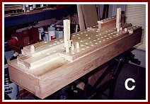
In PHOTO C one can see that the tapered pipe feet actually fit into
tapered holes in a board which sits above the openings in the chest.
Sandwiched in between is a slider with matching holes. This slider can
be moved lengthwise so the holes do not line up and thus cut off the air
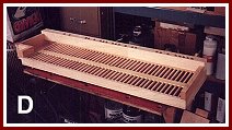
to that set of pipes. PHOTO D shows the underside of the wind chest at
this point in its construction. It is divided into channels, one for
each of the 41 notes.
Parts of the organ that need to be airtight, such as the wind chest, are
usually made of a dense, low porosity wood. Maple is an excellent choice
for this application. In addition it is a strong wood not prone to
splitting. PHOTO B shows the beginnings of the chest. If you look
closely you can see holes drilled in the top of the chest for the various
pipes. In reality the pipe feet do not fit directly into these holes.
In PHOTO C one can see that the tapered pipe feet actually fit into
tapered holes in a board which sits above the openings in the chest.
Sandwiched in between is a slider with matching holes. This slider can
be moved lengthwise so the holes do not line up and thus cut off the air
to that set of pipes. PHOTO D shows the underside of the wind chest at
this point in its construction. It is divided into channels, one for
each of the 41 notes.
 These channels line up with the openings for the pipes in the top of the chest. At the far side can be seen openings
through which air flows from a channel, through a connecting duct down to
one of the pipes which are mounted in the lower part of the organ. The
wooden strip across the channels provides a place to attach the hinges of
the pallet valves, one for each channel. PHOTO E shows the pallet valves
with their leather hinges glued into place. The remaining open area of
the channels is covered with an airtight cloth normally used to cover
small bellows. This can be seen as the red area behind the pallet
valves. In the next section I will go into a little more detail about
the pallet valves.
These channels line up with the openings for the pipes in the top of the chest. At the far side can be seen openings
through which air flows from a channel, through a connecting duct down to
one of the pipes which are mounted in the lower part of the organ. The
wooden strip across the channels provides a place to attach the hinges of
the pallet valves, one for each channel. PHOTO E shows the pallet valves
with their leather hinges glued into place. The remaining open area of
the channels is covered with an airtight cloth normally used to cover
small bellows. This can be seen as the red area behind the pallet
valves. In the next section I will go into a little more detail about
the pallet valves.
Editors note: Howard is a retired electrical engineer. Most of his
career was at the Army Night Vision and Electro-Optics Laboratory. He
became involved in mechanical music with the purchase of a non-working
player piano. As you will see in his articles, Howard is a highly skilled
craftsman. Building your own band organ is a real accomplishment and
Howard does beautiful work. Howard can be contacted at:
hwyman@tampabay.rr.com