by Howard Wyman
THE VACUUM BELLOWS
Previously we discussed the pressure bellows which furnish the air for the organ pipes that give the Wurlitzer Style 105 band organ its voice.
Wurlitzer band organs also have a vacuum bellows. The player mechanism is operated by this vacuum. The music for the organ is contained on paper rolls similar to player piano rolls, however each roll has about ten different tunes. Vacuum is used to read the holes in the paper roll and through a system of valves and pneumatics open the corresponding pallet valves in the windchest to send the pressurized air to the pipes. We will go into more detail on this subject later. The basic configuration of the vacuum bellows is similar to the pressure bellows but somewhat smaller. The difference is mainly in the configuration of the valves. Whereas the pressure bellows draw in air from the atmosphere and pressurize it, the vacuum bellows draw air from the player mechanism and exhaust it into the atmosphere.
 In retrospect it probably would have been smarter to build the vacuum
bellows before the pressure bellows since they are smaller and not as
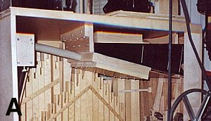
cumbersome, but then we all have 20/20 hindsight. The bellows can be
seen in PHOTO A in the top right area of the case. The dark triangular
area is the pumping part of the bellows. It appears dark in the
photograph because of the black leather covering. The box like assembly
attached to the bottom and to which the hose is attached is the cover for some of the valves which prevent reverse air flow. As in the pressure bellows, there are two almost identical units side by side and each unit has a stationary top board and bottom board with a movable center board forming two air chambers.
In retrospect it probably would have been smarter to build the vacuum
bellows before the pressure bellows since they are smaller and not as
cumbersome, but then we all have 20/20 hindsight. The bellows can be
seen in PHOTO A in the top right area of the case. The dark triangular
area is the pumping part of the bellows. It appears dark in the
photograph because of the black leather covering. The box like assembly
attached to the bottom and to which the hose is attached is the cover for some of the valves which prevent reverse air flow. As in the pressure bellows, there are two almost identical units side by side and each unit has a stationary top board and bottom board with a movable center board forming two air chambers.
The center board is moved up and down by a wooden rod connected to the crankshaft. As the center board moves it draws air into the chamber on one side through the common intake port. At the same time it is forcing the air out of the other chamber into the atmosphere. Check valves prevent the air from flowing the wrong direction. You may recall that the pressure for the pipes was regulated to a constant pressure by a reservoir which sat directly on top of the pressure bellows assembly. The vacuum system also uses a reservoir to maintain a constant negative pressure, however the vacuum reservoir is separate from the bellows. They are connected through a one inch ID hose. This hose can be seen in the above photograph. The pressure reservoir was held in a closed position by external springs, however the vacuum reservoir is held OPEN by internal springs. When the organ is operating the reservoir is drawn shut against the tension of the springs.
The amount of tension determines the level of suction that is maintained, which in this case is 20 inches water. A level lower than this is insufficient to operate the mechanism but then a level greater than 20 can also cause problems. I inadvertently had set the suction level to almost 30 inches and in playing a roll noticed that toward the end of the roll the tempo was slowing down. After I readjusted the level I did not have that problem so I came to the conclusion that the extra suction on the paper roll as it passed over the tracker bar holes was causing drag on the roll. The tension is set by bending the leaf springs inside the reservoir. For that purpose, the top board of the reservoir has a wooden plate which covers a large opening in the board. This plate is attached with screws and a leather gasket to make it airtight. The springs can be accessed by removing this plate. It usually takes a few tries before the correct level is obtained. The springs exert quite a bit of force and the only thing holding against this force is the leather covering of the reservoir. All of the time that the organ is sitting idle the force of the springs is keeping tension on the leather. In order to keep some of this pressure off the leather I put a reinforcing strap on the open end of the reservoir before gluing on the leather.
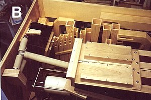 This strap is a piece of cotton belting about an inch wide, tacked and
glued at each end. PHOTO B is a view looking down at the top of the
organ with the top removed. At the right one can see the suction
bellows. The two box like structures are airtight covers for the valves
which only allow air to flow into the bellows. An internal passage from
these two covers goes to the valve cover on the bottom of the bellows
which we pointed out in the previous photograph and to which the hose
from the reservoir is attached. To the right of these covers there is a
maple support bracket which holds the bellows assembly together and to
the right of that the two dark strips are the leather flap valves which
allow air to be exhausted to the atmosphere during operation. In PHOTO
B one can also see the hose going from the bellows to a T-connector.
This strap is a piece of cotton belting about an inch wide, tacked and
glued at each end. PHOTO B is a view looking down at the top of the
organ with the top removed. At the right one can see the suction
bellows. The two box like structures are airtight covers for the valves
which only allow air to flow into the bellows. An internal passage from
these two covers goes to the valve cover on the bottom of the bellows
which we pointed out in the previous photograph and to which the hose
from the reservoir is attached. To the right of these covers there is a
maple support bracket which holds the bellows assembly together and to
the right of that the two dark strips are the leather flap valves which
allow air to be exhausted to the atmosphere during operation. In PHOTO
B one can also see the hose going from the bellows to a T-connector.
One leg of the T goes to the reservoir which is attached to the side of the case. The other leg of the T goes to a cut-out seen in the lower left.
This cut-out shuts off the vacuum to the player mechanism during rewinding of the roll, otherwise the organ would make some strange sounding music while rewinding.
Next we will see how this vacuum we have created is used to read the holes in the music roll and operate the valves and pneumatics to actually play the music.
Editors note: Howard is a retired electrical engineer and lives in Florida. Most of his career was at the Army Night Vision and Electro-Optics Laboratory. He became involved in mechanical music with the purchase of a non-working player piano. As you will see in his articles, Howard is a highly skilled craftsman. Building your own band organ is a real accomplishment and Howard does beautiful work. Howard can be contacted at: hwyman@tampabay.rr.com