by Howard Wyman
THE PNEUMATIC CHEST
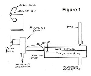 Let us take a look at the process by which a hole in the paper roll causes a pipe to play. A simplified diagram, FIGURE 1, is used to demonstrate. The vacuum that is generated by the bellows described in the previous section is applied to the pneumatic chest. On this chest is mounted a valve block for each note in the organ scale. A small amount of vacuum is passed through a tube from each valve block to the corresponding hole in the tracker bar. As the roll passes from the top spool down over the tracker bar to the bottom spool, a hole in the paper roll crossing over one of the holes in the tracker bar will allow air at atmospheric pressure to pass through the tube to the corresponding valve.
This causes the valve to operate and allow vacuum to go to the small pneumatic bellows mounted on the deck of the pneumatic chest. When the pneumatic is sucked shut it depresses a rod on the windchest causing the pallet valve to open and send wind through the channel for that note and to any pipe or pipes mounted on that channel.
 Before beginning construction of the pneumatic chest it is necessary to determine what valve blocks will be used. The dimensions in the Stanoszek plans are for Wurlitzer unit valve blocks just like the ones originally used by the Wurlitzer Company in the original band organs. If one is going to use another type of valve block it will be necessary to adjust the dimensions for that particular type. New Wurlitzer type valves are available from a couple of sources. Another type of valve that several builders have used is a valve block made from plastic commonly called the DOYLE LANE valve. I believe that these valves are
available from Doyle Lane or from the Player Piano Co. The height of these valves is greater than the Wurlitzer valves and so the vertical dimensions of the mounting surface on the pneumatic chest must be increased to make room for them. The horizontal dimensions stay the same.
Before beginning construction of the pneumatic chest it is necessary to determine what valve blocks will be used. The dimensions in the Stanoszek plans are for Wurlitzer unit valve blocks just like the ones originally used by the Wurlitzer Company in the original band organs. If one is going to use another type of valve block it will be necessary to adjust the dimensions for that particular type. New Wurlitzer type valves are available from a couple of sources. Another type of valve that several builders have used is a valve block made from plastic commonly called the DOYLE LANE valve. I believe that these valves are
available from Doyle Lane or from the Player Piano Co. The height of these valves is greater than the Wurlitzer valves and so the vertical dimensions of the mounting surface on the pneumatic chest must be increased to make room for them. The horizontal dimensions stay the same.
 I toyed with the idea of making my own valve blocks. A set of drawings for the Wurlitzer style valve is sold by Player Piano Co. I built a couple for practice and was successful although it looked like a job that would take some time. Of course most of the work on the organ had been time consuming so this would not necessarily be any different. Fortunately I was talking to a friend who does a lot of restoration and construction of mechanical musical instruments and he asked, How many valves do you need? He gave me a box full of old Wurlitzer valves. The
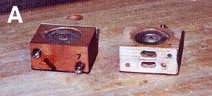
only catch was that they all needed to be rebuilt, but then that would be easier than building them from scratch. I had rebuilt quite a few valves in the past while restoring several player pianos so I was pretty much familiar with the process. PHOTO A shows a front and back view of two restored valve blocks. In the view on the left one can see the brass nipple sticking out at an angle that the tube from the tracker bar attaches to. You can also see the two mounting screws which are used to attach the valve block to the chest. There is a small coil spring under
the head of each screw. This serves to hold the block firmly airtight against the chest when the wood swells or shrinks in changing humidity.
I toyed with the idea of making my own valve blocks. A set of drawings for the Wurlitzer style valve is sold by Player Piano Co. I built a couple for practice and was successful although it looked like a job that would take some time. Of course most of the work on the organ had been time consuming so this would not necessarily be any different. Fortunately I was talking to a friend who does a lot of restoration and construction of mechanical musical instruments and he asked, How many valves do you need? He gave me a box full of old Wurlitzer valves. The
only catch was that they all needed to be rebuilt, but then that would be easier than building them from scratch. I had rebuilt quite a few valves in the past while restoring several player pianos so I was pretty much familiar with the process. PHOTO A shows a front and back view of two restored valve blocks. In the view on the left one can see the brass nipple sticking out at an angle that the tube from the tracker bar attaches to. You can also see the two mounting screws which are used to attach the valve block to the chest. There is a small coil spring under
the head of each screw. This serves to hold the block firmly airtight against the chest when the wood swells or shrinks in changing humidity.
In the right hand view the lower oval shaped opening is the pathway for the constant vacuum from the pneumatic chest to the valve. The upper opening goes to a passageway in the chest which goes to the small pneumatic bellows which operates the pallet valve in the wind chest. A leather gasket is placed between the valve block and the pneumatic chest in order to make an airtight seal.
 The vertical board to which the valves are mounted is made up of two or three layers. The method I used was to start with a board for the side that faces the front of the organ. I then glued wood strips to that to form the channels for the vacuum which goes to the bottom openings of all the valves. The third layer was then glued on top of that forming the back surface of the chest. After all of the holes have been drilled for the air passages to the valve blocks and also to the deck board with the pneumatics, all of these internal passages should be sealed to make them airtight. I covered all of the openings on the front and back of the chest with masking tape, then with the chest upside down I poured shellac into the drill holes in the bottom of the chest. After making sure that the sealant has run all through the chest the shellac is poured out, the masking tape is removed, and the chest is allowed to dry. The same should be done to the passages in the deck board. The deck is attached to the chest with long screws through the chest and into the deck. Care should be taken to drill the screw holes in between the channels in the chest. Flat head screws should be used because some of them will be partially under a valve.
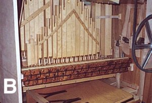
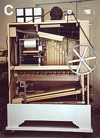
In PHOTO B one can see the three rows of valves mounted on the pneumatic chest and the chest mounted in the organ. The tips of the fingers on the small pneumatic bellows are just barely visible beyond the top edge of the chest. PHOTO C was taken after the shelf for the spool frame was mounted in the cabinet. The organ is now ready for a final tuning and then to play a roll, without drums and cymbal of course. A few minor adjustments had to be made, but it would be hard to describe the exhilaration I felt when the strains of THE BLUE DANUBE echoed through the workshop. Now to add the percussion.
Editors note: Howard is a retired electrical engineer and lives in Florida. Most of his career was at the Army Night Vision and Electro-Optics Laboratory. He became involved in mechanical music with the purchase of a non-working player piano. As you will see in his articles, Howard is a highly skilled craftsman. Building your own band organ is a real accomplishment and Howard does beautiful work. Howard can be contacted at: hwyman@tampabay.rr.com