Part 3 by Howard Wyman
At the beginning of this project I built a few flute pipes primarily to see if I had the ability to build a pipe that would make a proper sound. My reasoning was that if I couldn't build a decent sounding pipe then there was no point in proceeding with the rest of the project. After building about five stopped flutes, I went on to the construction of the wind chest as I have described in previous articles. With that done, it was time to return to the making of pipes.
 I decided to build the set of 14 melody flageolets next. As it turns out
this may not have been the wisest choice since I had more problems with
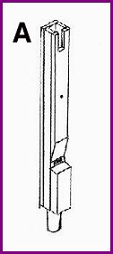
this set of pipes that I did with any of the others. FIGURE A is a
sketch of a typical flageolet. It is of similar construction to an open
flute with the addition of a nodal hole at about the mid-point of its
length. The frequency at which a pipe sounds is determined by its
length. The effect of the nodal hole is to cause the pipe to sound an
octave higher than it would for that length but without the hole. The
slot at the top of the pipe is for tuning. A brass plate in this slot is
moved up or down to tune the pipe to the desired frequency by effectively
changing the apparent length of the pipe. At first I was uncertain how
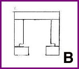
this plate should be configured so that it could be adjusted. The method
I finally used was to employ a small router to cut a rabbet in the front
edge of the pipe sides before gluing on the front. The depth of this
rabbet should be the same as the thickness of the brass plate. FIGURE B
is a view looking down at the top of the pipe. It can be seen that after
the front of the pipe is attached a groove is formed on each side of the
pipe for the brass plate to slide into.
I decided to build the set of 14 melody flageolets next. As it turns out
this may not have been the wisest choice since I had more problems with
this set of pipes that I did with any of the others. FIGURE A is a
sketch of a typical flageolet. It is of similar construction to an open
flute with the addition of a nodal hole at about the mid-point of its
length. The frequency at which a pipe sounds is determined by its
length. The effect of the nodal hole is to cause the pipe to sound an
octave higher than it would for that length but without the hole. The
slot at the top of the pipe is for tuning. A brass plate in this slot is
moved up or down to tune the pipe to the desired frequency by effectively
changing the apparent length of the pipe. At first I was uncertain how
this plate should be configured so that it could be adjusted. The method
I finally used was to employ a small router to cut a rabbet in the front
edge of the pipe sides before gluing on the front. The depth of this
rabbet should be the same as the thickness of the brass plate. FIGURE B
is a view looking down at the top of the pipe. It can be seen that after
the front of the pipe is attached a groove is formed on each side of the
pipe for the brass plate to slide into.
 The first step in building a pipe of this type is to cut a piece of maple
with the dimensions of the inside width and depth of the pipe. This will
be used for the block. It should be long enough to make the block plus
one or two pieces to be used as spacers when gluing the pipe together.
The spacers will insure that the inside dimensions are consistent
throughout the length of the pipe. After the glue sets they will be
removed. Next the sides of the pipe are glued to the block. I made the
side pieces a little bit wide and when I glued them on I made certain
they were flush with the front edge of the block. After the glue set I
planed the excess from the rear edge of each side until it was also flush
with the block. Next the back was glued on. I also made this piece
slightly wide and after the glue was set it was planed until it formed a
smooth joint with the sides. Before attaching the front of the pipe it
is necessary to cut the chamfer which will be just above the mouth of the
assembled pipe. I experimented with several methods of doing this and
the method I had the most success with is as follows. Using a pencil, I
marked the top and bottom of the chamfer. Turn the board over and mark
the bottom of the chamfer on that side also, then using a sharp knife cut
across the board on this line. This will give a clean edge to the bottom
of the chamfer as the material is cut away. There is a very good
description of the construction of wood pipes in "The Art of Organ
Building" by George Ashdown Audsley, Chapter 34. I would recommend
reading it before beginning construction of any wooden pipes. Next, on
the edge of the front board of the pipe I drew a line from the upper edge
of the chamfer at the front of the board to the lower edge of the chamfer
on the rear of the board. This showed the angle of the chamfer. I then
clamped the board face-up into a drill press vise. I aligned the marks
on the edge of the board with the top edge of the jaws of the vise. I
then put a 1/4 inch router bit in the chuck of the drill press and
adjusted the speed to the highest setting. I could then remove material
by sliding the vise across the drill press table. Since the speed of the
drill press, even at its highest setting, was still much less than the
speed of a typical router I could only make shallow cuts, therefore it
was necessary to make a series of shallow cuts in order to remove enough
material. When I got close to the desired result, I finished shaping the
chamfer by hand. I made some home made files by cutting strips of wood
and gluing various grades of sandpaper onto them. These are handy not
only for the final shaping of the chamfer, but also the filing of the
windway in the block.
The first step in building a pipe of this type is to cut a piece of maple
with the dimensions of the inside width and depth of the pipe. This will
be used for the block. It should be long enough to make the block plus
one or two pieces to be used as spacers when gluing the pipe together.
The spacers will insure that the inside dimensions are consistent
throughout the length of the pipe. After the glue sets they will be
removed. Next the sides of the pipe are glued to the block. I made the
side pieces a little bit wide and when I glued them on I made certain
they were flush with the front edge of the block. After the glue set I
planed the excess from the rear edge of each side until it was also flush
with the block. Next the back was glued on. I also made this piece
slightly wide and after the glue was set it was planed until it formed a
smooth joint with the sides. Before attaching the front of the pipe it
is necessary to cut the chamfer which will be just above the mouth of the
assembled pipe. I experimented with several methods of doing this and
the method I had the most success with is as follows. Using a pencil, I
marked the top and bottom of the chamfer. Turn the board over and mark
the bottom of the chamfer on that side also, then using a sharp knife cut
across the board on this line. This will give a clean edge to the bottom
of the chamfer as the material is cut away. There is a very good
description of the construction of wood pipes in "The Art of Organ
Building" by George Ashdown Audsley, Chapter 34. I would recommend
reading it before beginning construction of any wooden pipes. Next, on
the edge of the front board of the pipe I drew a line from the upper edge
of the chamfer at the front of the board to the lower edge of the chamfer
on the rear of the board. This showed the angle of the chamfer. I then
clamped the board face-up into a drill press vise. I aligned the marks
on the edge of the board with the top edge of the jaws of the vise. I
then put a 1/4 inch router bit in the chuck of the drill press and
adjusted the speed to the highest setting. I could then remove material
by sliding the vise across the drill press table. Since the speed of the
drill press, even at its highest setting, was still much less than the
speed of a typical router I could only make shallow cuts, therefore it
was necessary to make a series of shallow cuts in order to remove enough
material. When I got close to the desired result, I finished shaping the
chamfer by hand. I made some home made files by cutting strips of wood
and gluing various grades of sandpaper onto them. These are handy not
only for the final shaping of the chamfer, but also the filing of the
windway in the block.
 After the chamfer is shaped the front can be glued on the pipe. Next the
windway is formed by filing the front of the block at approximately the
same angle as the chamfer. While filing, periodically lay the cap on the
front and measure the windway slot with a feeler gauge. Before gluing on
the cap, I would place the pipe on the windchest, adjust the wind
pressure to the proper setting, and while the pipe was sounding I would
move the cap up and down a small amount until I got the desired tone. I
would then mark that position so the cap could be glued on accurately.
After the chamfer is shaped the front can be glued on the pipe. Next the
windway is formed by filing the front of the block at approximately the
same angle as the chamfer. While filing, periodically lay the cap on the
front and measure the windway slot with a feeler gauge. Before gluing on
the cap, I would place the pipe on the windchest, adjust the wind
pressure to the proper setting, and while the pipe was sounding I would
move the cap up and down a small amount until I got the desired tone. I
would then mark that position so the cap could be glued on accurately.
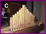
I mentioned earlier that this set of pipes gave me more problems that any of the others. The main problem was "overblowing" in that the pipe was not stable at its fundamental frequency but would break into a tone an octave higher. I finally solved this problem by making the wind hole in the foot of the pipe slightly smaller than called for in the plans. The completed set of flageolet pipes are shown mounted on the wind chest in FIGURE C.
Editors note: Howard is a retired electrical engineer and lives in Florida. Most of his career was at the Army Night Vision and Electro-Optics Laboratory. He became involved in mechanical music with the purchase of a non-working player piano. As you will see in his articles, Howard is a highly skilled craftsman. Building your own band organ is a real accomplishment and Howard does beautiful work. Howard can be contacted at: hwyman@tampabay.rr.com