by Howard Wyman
BUILDING THE CABINET
 Now that the windchest and pipes for the band organ had been completed
this seemed to be a good time to start building the cabinet in order to
be able to install not only the windchest but the remaining components as
they are built. I had decided earlier in the project to paint the
cabinet in a manner similar to the later model 105. That allowed me to
use 3/4 inch birch plywood for most of the cabinet. If the builder
chooses to have a finished oak cabinet like the early models he could use
an oak veneered plywood. For the front of the cabinet I used 3/4 inch
clear pine boards doweled and glued together. I started by attaching the
front to the sides using dowels and glue. This was then attached to the
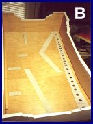
floor of the cabinet using screws. Before installing the floor I laid
out the positions of the pipes that would be installed beneath the floor
and cut the holes for the passage of air to the pipes. It was necessary
to calculate the distance from the holes to the front of the cabinet so
that they would line up with the row of holes in the bottom front of the
windchest. PHOTO B shows the bottom of the floor and the positions of
the holes. One can also see the suede leather strips on which the pipes
will be glued. I should also mention that I added about three inches to
the height of the sides and front. In adding up the various dimensions
it appeared that there was not enough height to accommodate the tallest
trumpet pipe. As you can see in the photographs this probably would have
been the case.
Now that the windchest and pipes for the band organ had been completed
this seemed to be a good time to start building the cabinet in order to
be able to install not only the windchest but the remaining components as
they are built. I had decided earlier in the project to paint the
cabinet in a manner similar to the later model 105. That allowed me to
use 3/4 inch birch plywood for most of the cabinet. If the builder
chooses to have a finished oak cabinet like the early models he could use
an oak veneered plywood. For the front of the cabinet I used 3/4 inch
clear pine boards doweled and glued together. I started by attaching the
front to the sides using dowels and glue. This was then attached to the
floor of the cabinet using screws. Before installing the floor I laid
out the positions of the pipes that would be installed beneath the floor
and cut the holes for the passage of air to the pipes. It was necessary
to calculate the distance from the holes to the front of the cabinet so
that they would line up with the row of holes in the bottom front of the
windchest. PHOTO B shows the bottom of the floor and the positions of
the holes. One can also see the suede leather strips on which the pipes
will be glued. I should also mention that I added about three inches to
the height of the sides and front. In adding up the various dimensions
it appeared that there was not enough height to accommodate the tallest
trumpet pipe. As you can see in the photographs this probably would have
been the case.
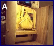
 The windchest was then installed in the cabinet. I attached wooden
strips to the inside of the cabinet sides and the windchest rests on
these strips. In the plans it indicates that the chest is held down by
long screws which go through the chest and into the wooden strips.
However screws long enough to do that were impossible to find. Instead I
screwed brackets above the chest to hold it down. PHOTO A shows the
windchest installed in the cabinet. With the wind chest in place it was
now possible to determine the position of the air passages in the riser
block. This is the block that contains the passageways from the wind
chest to the pipes beneath the floor. To make a pattern I cut a thick
piece of cardboard of the proper length and with a height which fit
exactly between the front of the windchest and the floor. After putting
it in position I marked the locations of the openings in the bottom of
the windchest and also the openings in the floor. I then removed it from
the organ and drew in the locations of the passages to connect the upper
holes to the corresponding lower holes. This pattern was then used to
make the riser block.
The windchest was then installed in the cabinet. I attached wooden
strips to the inside of the cabinet sides and the windchest rests on
these strips. In the plans it indicates that the chest is held down by
long screws which go through the chest and into the wooden strips.
However screws long enough to do that were impossible to find. Instead I
screwed brackets above the chest to hold it down. PHOTO A shows the
windchest installed in the cabinet. With the wind chest in place it was
now possible to determine the position of the air passages in the riser
block. This is the block that contains the passageways from the wind
chest to the pipes beneath the floor. To make a pattern I cut a thick
piece of cardboard of the proper length and with a height which fit
exactly between the front of the windchest and the floor. After putting
it in position I marked the locations of the openings in the bottom of
the windchest and also the openings in the floor. I then removed it from
the organ and drew in the locations of the passages to connect the upper
holes to the corresponding lower holes. This pattern was then used to
make the riser block.
 I made the riser block by forming a sandwich of 1/4 inch plywood on each
side of 3/4 inch wood. The 3/4 inch wood is cut to form the passageways
and glued onto one of the pieces of plywood. The other piece of plywood
is then glued onto the remaining side. There should be no leakage from
one passageway to the next. After the riser is glued together the
passageways should be sealed with shellac or some other sealer. I used a
product called Phenoseal which I obtained from The Player Piano Co.
Next, the riser was attached to the floor with the air passages lined up
with the holes in the floor. The plan is rather sketchy as to how the
riser is attached. I used screws up through the floor and into the
bottom of the riser.
I made the riser block by forming a sandwich of 1/4 inch plywood on each
side of 3/4 inch wood. The 3/4 inch wood is cut to form the passageways
and glued onto one of the pieces of plywood. The other piece of plywood
is then glued onto the remaining side. There should be no leakage from
one passageway to the next. After the riser is glued together the
passageways should be sealed with shellac or some other sealer. I used a
product called Phenoseal which I obtained from The Player Piano Co.
Next, the riser was attached to the floor with the air passages lined up
with the holes in the floor. The plan is rather sketchy as to how the
riser is attached. I used screws up through the floor and into the
bottom of the riser.
 To prevent air leakage I glued a leather gasket to
both the bottom and top of the riser before installing it. The windchest
was then secured to the top of the riser block. As I stated earlier I
was not able to obtain screws long enough to do this. Instead I used 1/4
inch lag screws. A countersink has to be drilled in the top of the chest
so that the top of the head of the lag screw is flush with the top of the
windchest. A couple of the screws are located underneath the strip which
holds the piccolos and flageolets so the heads have to be countersunk.
This also means that the strip has to be removed while the windchest is
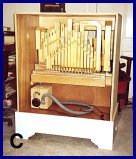
being anchored down. PHOTO C shows the cabinet with the riser block in
place. The box sitting in the bottom of the cabinet is the blower box
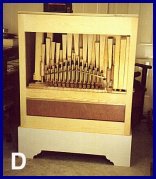
which I used to test individual pipes. Finally, in PHOTO D one can see
the front of the untrimmed cabinet with the wind chest and riser block
installed. Gradually it is beginning to look like a band organ.
To prevent air leakage I glued a leather gasket to
both the bottom and top of the riser before installing it. The windchest
was then secured to the top of the riser block. As I stated earlier I
was not able to obtain screws long enough to do this. Instead I used 1/4
inch lag screws. A countersink has to be drilled in the top of the chest
so that the top of the head of the lag screw is flush with the top of the
windchest. A couple of the screws are located underneath the strip which
holds the piccolos and flageolets so the heads have to be countersunk.
This also means that the strip has to be removed while the windchest is
being anchored down. PHOTO C shows the cabinet with the riser block in
place. The box sitting in the bottom of the cabinet is the blower box
which I used to test individual pipes. Finally, in PHOTO D one can see
the front of the untrimmed cabinet with the wind chest and riser block
installed. Gradually it is beginning to look like a band organ.
Editors note: Howard is a retired electrical engineer and lives in Florida. Most of his career was at the Army Night Vision and Electro-Optics Laboratory. He became involved in mechanical music with the purchase of a non-working player piano. As you will see in his articles, Howard is a highly skilled craftsman. Building your own band organ is a real accomplishment and Howard does beautiful work. Howard can be contacted at: hwyman@tampabay.rr.com